MicroPython for your cat (WiPy food dispenser)
To my knowledge there are two ways to feed a cat:
- Always have food out (unhealthy & what goes in must come out)
- Give a set amount of food each day (healthy but tedious)
So I would prefer the second option and control the food intake of my cat (cats actually). This seems like an easily automatable problem.
Step 1, buy an automatic cat dispensing unit.
Step 2, profit.
The problem is that these devices aren’t really cat proof, see:
Exhibit A: cat brain over machine
Exhibit B: cat brawn over machine (turn off sound if you can)
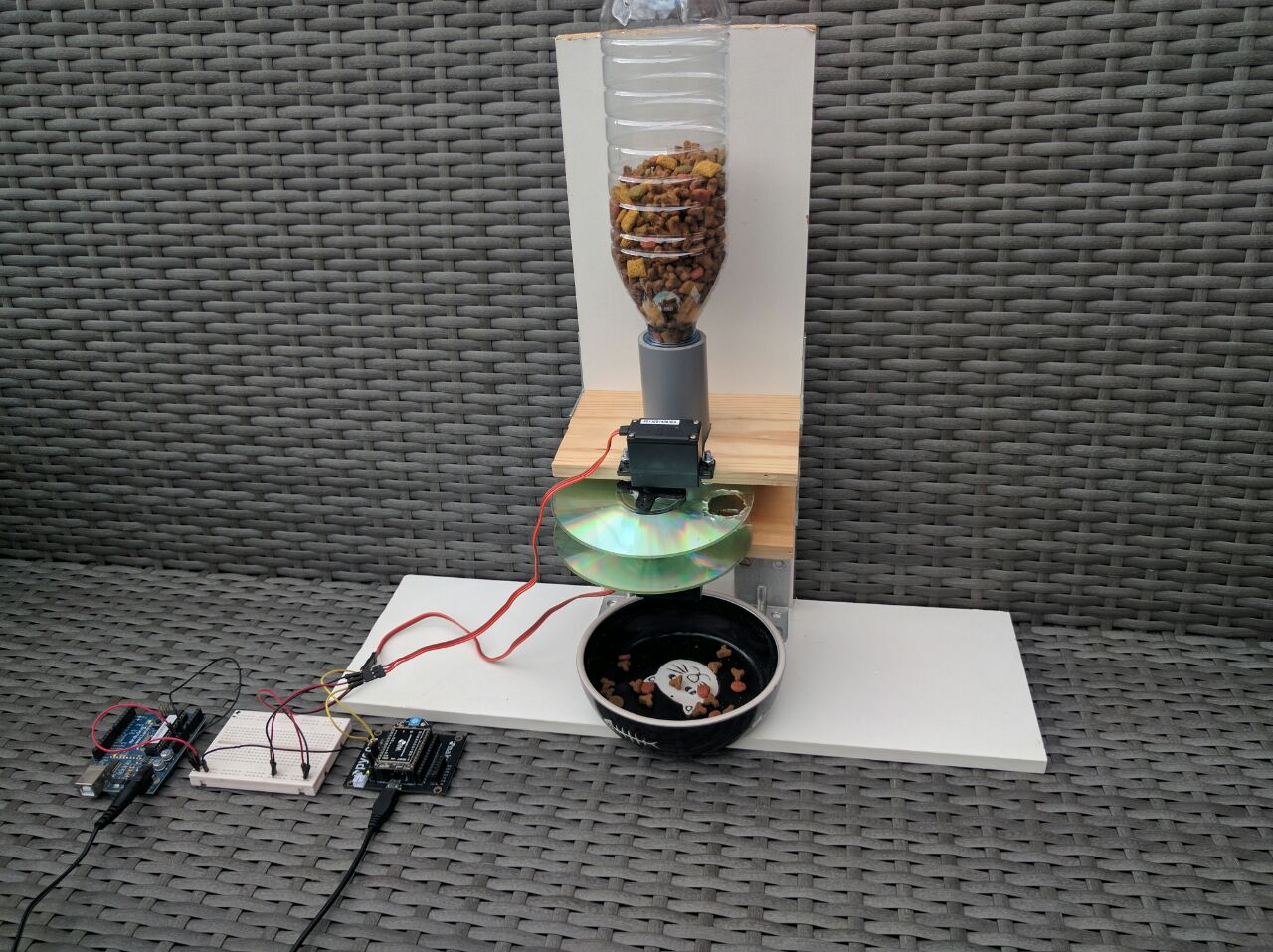
So, great idea, instead of buying an off the shelf food dispenser, lets create our own, do it yourself, cat feeder! Tada:
@youtube WiPy powered cat food dispenser, prototype. Yes, there is also an Arduino in the video, but it only acts as a power supply :)
Hmmm, not quite as polished as I had envisioned. It is more like a basic prototype. But it did teach me how to control hobby servo’s with the WiPy. Which coming from a Arduino & Raspberry Pi background is not as simple as one would expect. It’s not just a case of making some library calls. You’ll have to work with timers and do some actual calculations.
So in this post we’ll see how to use the on board timers to send a pulse width modulated (PWM) signal to a servo. If you are unfamiliar with the WiPy development board, have a look at the getting started blog post. Otherwise read on, you’ll learn how to:
- Calculate PWM configuration values for a servo angle
- Use timers to send a PWM signal on the WiPy
- How to make a DIY cat feeder, though be warned, it is not production ready
Servo wiring
Wiring a servo is pretty straight forward.
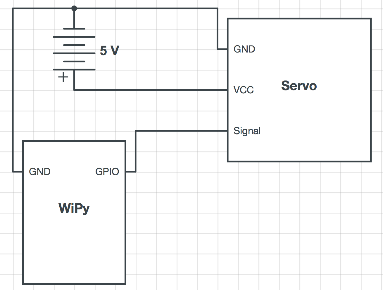
For the servo in this post we supply 5V to the vcc (red) wire. GND connects to the servo brown wire (often black). And the remaining wire carries our signal and connects to the GPIO pin of the WiPy.
The servo power comes from a second power supply. To get the two power supplies to work in sync we’ll connect the grounds.
Servo control
To control the hobby servos we’ll need to send PWM (Pulse Width Modulation) signals. To create a PWM signal the WiPy has a set of special pins that connect to hardware timers. We’ll look how to calculate the right PWM values and see how to configure a timer so it sends the right signal.
PWM
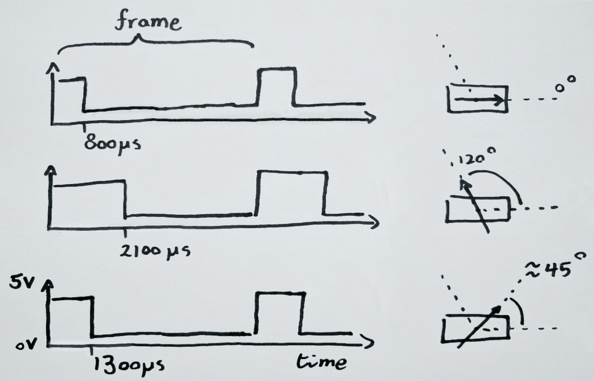
A PWM signal is used to control most hobby servos. This signal is an series of high and low voltages. The width the high voltage is varied but the cycle as a whole has a fixed length (see image below). The servo we’ll use here has a PWM pulse width between 800µs and 2100µs (full specs). Meaning, a signal of 800µs will correspond to a servo angle of 0 degrees. And a signal of 2100µs will correspond to the full servo rotation angle of 120 degrees. It is simplest to see as a diagram:
The duty cycle on the WiPy timers control the PWM signal. The duty cycle is the fraction of an entire PWM signal that has high voltage. The duty cycle for a target servo angle is calculated as follows. First we calculate the fraction the target angle is of the full servo range. Next the pulse width of the target angle is calculated. Finally we use the pulse width to determine the duty cycle.
1) Calculate the angle fraction
For the width calculation we need to know what fraction the target angle is of the full servo range. In Python code this accounts to:
angle_fraction = angle / ROTATIONAL_RANGE
2) Angle fraction to pulse width
We calculate the pulse width from the angle fraction:
pulse_width = PULSE_MIN + angle_fraction * (PULSE_MAX — PULSE_MIN)
3) Pulse width to percentage of PWM frame
The WiPy PWM signal is controlled by a timer that takes the signal frequency and duty cycle as an input. For this servo a frequency of 50Hz works well. The duty cycle is the percentage of a single PWM pulse that is high voltage.
The PWM signal frame is duration of a full signal cycle (high and low part). Given the frequency we calculate it by:
frame = 1 second / FREQUENCY
The fraction the signal is high vs low, the duty cycle, is obtained using:
duty_cycle = pulse_width / frame
This equates to the duty cycle as a fraction of a full frame. But that is not what we need. The API requires it to be in 1/100th of percentages. This is because we don’t have the luxury of floating point arithmetic. The drawback of having only integers is that our calculations are way off.
Math magic to circumvent lack of floating point support
Not have floating point operations in the WiPy is a bit of a hassle. But we can still do our calculations by shifting all our calculations well clear of the zero. Remember that we can multiply an equation on both sides and still have it remain true.
The following code has accurate calculations, by multiplying the equations by 100. Care is taken to multiply first and do integer division as late as possible:
# angle100 target angle in degrees * 100
# ROTATIONAL_RANGE_100 is servo full rotation in degrees * 100
# PULSE_MIN & PULSE_MAX are in µs
# PERC_100 is 100% * 100

angle_fraction = PERC_100 * angle100 // ROTATIONAL_RANGE_100  # in 100% * 100 format
pulse_width = PULSE_MIN + angle_fraction * (PULSE_MAX — PULSE_MIN)// PERC_100  # in µs
frame = 1000000µs // FREQUENCY
duty_cycle = PERC_100 * pulse_width // frame
Timer to PWM signal
Instead of writing the signal timing code ourselves, we we use the timer on the board. We control what percentage of each frame the signal is high by setting the duty cycle. At a hardware level the timer connects to an output pin.
A couple of pins on the WiPy support PWM. Yet actually controlling such a pin through a timer is bit tricky. The information is available in the pinout image. See the table for the same information but reformatted
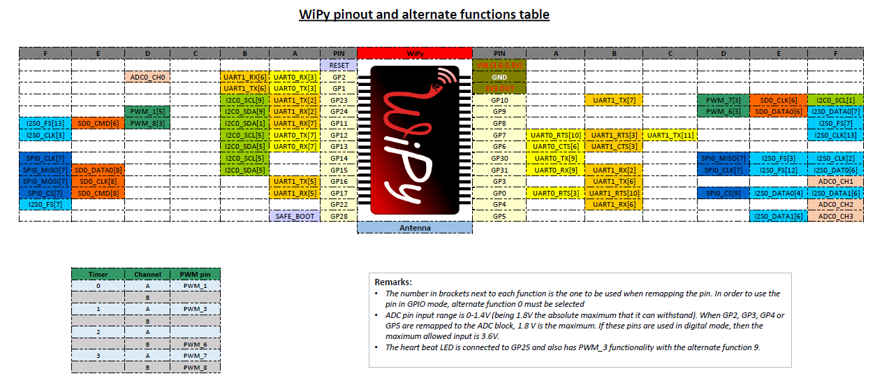
+----------+----------+-----+-------+---------------+
| GPIO pin | Alt code | PWM | Timer | Timer channel |
+----------+----------+-----+-------+---------------+
|        9 |        3 |   6 |     2 | B             |
|       10 |        3 |   7 |     3 | A             |
|       11 |        3 |   8 |     3 | B             |
|       24 |        5 |   1 |     0 | A             |
+----------+----------+-----+-------+---------------+
We’ll use GP pin 9 to control our servo. The pin is controlled by timer 2, channel B. The pin will follow the timer by setting the pin alt function to 3. In Python code this is done by:
Pin(9, mode=Pin.ALT, alt=3)
timer = Timer(2, mode=Timer.PWM)
channel = timer.channel(Timer.B, freq=freq)
For more details see the timer documentation and channel documentation.
The fraction of the PWM frame for which the pin has a high output is determined by the duty cycle. We set the duty cycle using:
self.channel.duty_cycle(duty_cycle)
Angle to actuation
We can now configure a pin timer combination and provide it with the correct duty cycle value. So putting it all together, we can now make a servo loop through its full rotational range:
#
# Rotate servo over full rotational range
#
import time
from machine import Pin, Timer

# Servo specific constants
PULSE_MIN = 900  # in us, actually bit higher than specs indicate
PULSE_MAX = 2100  # in us
FREQUENCY = 50  # Hz
ROTATIONAL_RANGE_100 = 12000  # 120deg * 100

# Helper constants
PERC_100 = 10000  # in 100% * 100
SERVO_WAIT = 100  # in ms

led = Pin('GP25', mode=Pin.OUT)
led(0)  # turn off the heartbeat LED

Pin('GP9', mode=Pin.ALT, alt=3)
timer = Timer(2, mode=Timer.PWM)
channel = timer.channel(Timer.B, freq=FREQUENCY)


def set_angle(angle):
    angle100 = angle * 100  # in degrees * 100
    angle_fraction = PERC_100 * angle100 // ROTATIONAL_RANGE_100  # in 100% * 100 format
    pulse_width = PULSE_MIN + angle_fraction * (PULSE_MAX - PULSE_MIN) // PERC_100  # in µs
    frame = 1000000 // FREQUENCY  # in µs
    duty_cycle = PERC_100 * pulse_width // frame  # in 100% * 100 format
    channel.duty_cycle(duty_cycle)


for angle in range(0, 120):
    set_angle(angle)
    time.sleep_ms(SERVO_WAIT)

led(1)  # turn on the heartbeat LED
Below you can see the video of a WiPy running the code above.
Servo going through full rotation using PWM signal through WiPy timer.
Servo library
As a final step, we can refactor everything so the math and configuration is removed from our business logic. Or we can just use the WiPy servo library I created by doing just that. If we use that library, we can simplify the code from before to:
# coding=utf-8
#
# Rotate servo over full rotational range
#
import time
from machine import Pin

from servo import Servo

# Configuration
SERVO_WAIT = 100  # in ms
servo_pin = 9  # GP pin

# Servo specific constants
PULSE_MIN = 900  # in µs, actually bit higher than specs indicate
PULSE_MAX = 2100  # in µs
FREQUENCY = 50  # Hz
ROTATIONAL_RANGE_100 = 12000  # 120deg * 100

led = Pin('GP25', mode=Pin.OUT)
led(0)  # turn off the heartbeat LED

servo = Servo(servo_pin,
              FREQUENCY,
              ROTATIONAL_RANGE_100,
              PULSE_MIN,
              PULSE_MAX)

for angle in range(0, 120):
    servo.angle(angle * 100)
    time.sleep_ms(SERVO_WAIT)

led(1)  # turn on the heartbeat LED
You can upload it by cloning the servo lib next to the “main.py” file:
git clone [email protected]:RRMoelker/WiPy-servo.git
Then upload both the “main.py” and “servo.py” files by creating the following file:
#!/bin/bash

# first argument is WiPy ip

lftp -u micro,python $1 << EOF

cd /flash
put main.py
put WiPy-servo/servo.py

bye
EOF
Call the upload script with your WiPy ip using:
sh ./upload.sh <the.wi.py.ip>
Putting it to work
The whole point of controlling some hobby servos was to create a cat food dispenser. We’ll have a quick look at the dispenser in this project. Do note, that it does not perform as well as I hoped, so view it as a nice experiment rather than a blueprint on how to make one. For what I can tell there a two types of mechanisms to control the “flow” of food.
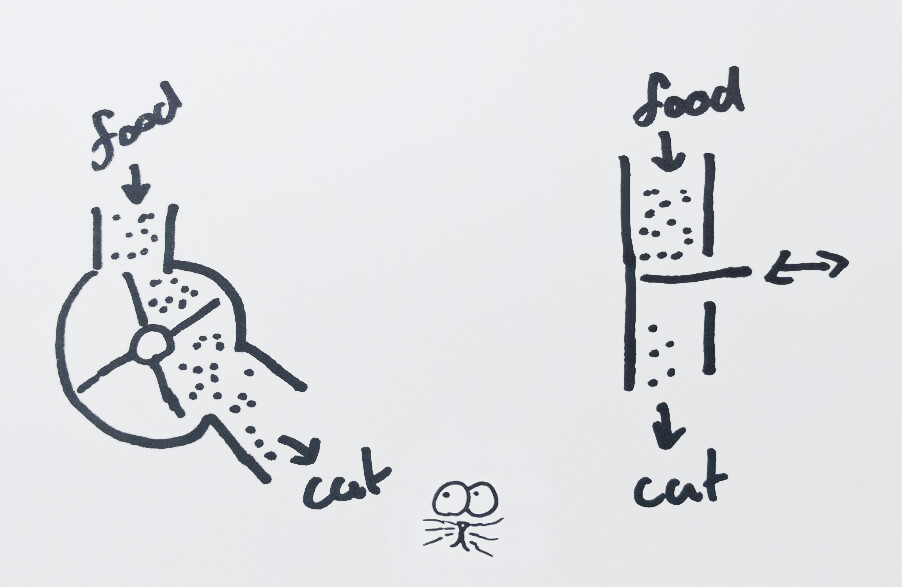
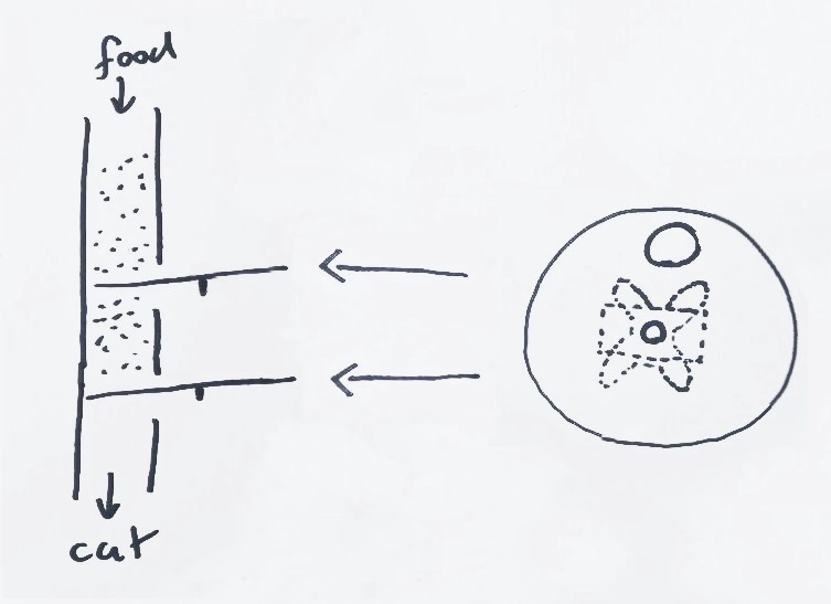
I opted for the second option. And by using two sliding latches we can more accurately dose the food portions.
I used an old CD with a hole the size of the inner tube glued to a servo to open and close a single port. The mechanism allows to ration portions of about 10 grams.
The dispenser food cycle code opens and closes the top and bottom servos. It intentionally stutters at a few set angles so that pieces of food that become lodged have a chance to slip free.
The python code for a single dispense cycle is as follows:
# coding=utf-8
#
# Loop through food delivery cycle
#
import time
from machine import Pin

from servo import Servo

led = Pin('GP25', mode=Pin.OUT)
led(0)  # turn off the heartbeat LED

SERVO_WAIT = 50

# Servo specific constants
PULSE_MIN = 900  # in µs, actually bit higher than specs indicate
PULSE_MAX = 2100  # in µs
FREQUENCY = 50  # Hz
ROTATIONAL_RANGE_100 = 12000  # 120deg * 100

servo_top = Servo(10, FREQUENCY, ROTATIONAL_RANGE_100, PULSE_MIN, PULSE_MAX)
servo_bottom = Servo(9, FREQUENCY, ROTATIONAL_RANGE_100, PULSE_MIN, PULSE_MAX)

top_servo_limits = {
    'open': 0,  # deg
    'stutter': [75, 74, 73],  # deg
    'closed': 100,  # deg
    'direction': -1,  # angle direction from closed to open
}

bottom_servo_limits = {
    'open': 120,  # deg
    'stutter': [90, 100, 110],
    'closed': 20,  # deg
    'direction': 1,  # # angle direction from closed to open
}


def get_next_stutter(stutter_array):
    if (len(stutter_array) > 0):
        return stutter_array.pop()
    else:
        return None


def set_angle(servo, angle):
    servo.angle(angle * 100)
    time.sleep_ms(SERVO_WAIT)


def move_servo(servo, from_angle, to_angle, dir, stutter_array=[]):
    """
    Open or close servo, possibly shutters a bit to prevent jamming
    """
    stutter = get_next_stutter(stutter_array)

    range1 = range(from_angle, to_angle, dir)
    for angle in range1:
        set_angle(servo, angle)

        if angle == stutter:
            stutter_angles = range(angle + -15 * dir, angle, dir)
            for angle in stutter_angles:
                set_angle(servo, angle)
            stutter = get_next_stutter(stutter_array)


def cycle_servo(servo, limits):
    """
    Open and close servo
    """
    print('opening')
    move_servo(servo, limits['closed'], limits['open'], limits['direction'])

    print('closing')
    move_servo(servo, limits['open'], limits['closed'], limits['direction'] * -1, limits['stutter'])


cycle_servo(servo_top, top_servo_limits)
cycle_servo(servo_bottom, bottom_servo_limits)

led(1)  # turn on the heartbeat LED
The dispenser works. But it does jam occasionally, so I wouldn’t use it for long periods while I’m away. That unfortunately defeats the point of making an automatic dispenser. So it is definitely not “production” ready.
That said, even though the jamming is a problem, it is a recoverable one. The servo jams while closing, not while opening, so if it does jam we can always open it. Of course that may open the food floodgates. But worse comes to worse, you aren’t likely to starve your cat short of a electrical failure.
Of course there are some other glaring problems with this system. Like not having a casing and having little spacing for a cat to eat. Any future version will surely fix those issues. And it would make use of interrupt sensors to provide feedback whether food is actually dispensed.
Servo food serving
This should have gotten you started controlling servo’s using a PWM signal. And you should be able to control a servo using the WiPy on board timers. Finally, I hope the cat dispenser design has inspired some of you to create your own system. Please let me know when you come up with a working cat proof design :).
Related
This post is part of the project MicroPython for your cat (WiPy food dispenser)
- Previous post: WiPy getting started