Modifying security camera IR LED ring
Identifying a marker in an image is done by having it reflect infrared light back to the camera. For this to work, a IR light source should be close to the camera. The most common solution is to put an IR LED ring around the camera lens. Here we'll look at using a more generic security IR LED ring for this purpose.
IR LED ring
Obtaining an IR LED ring for this project was a bit trickier than expected. I could not find a straight-up IR LED ring with no additional circuity that shipped in reasonable time.
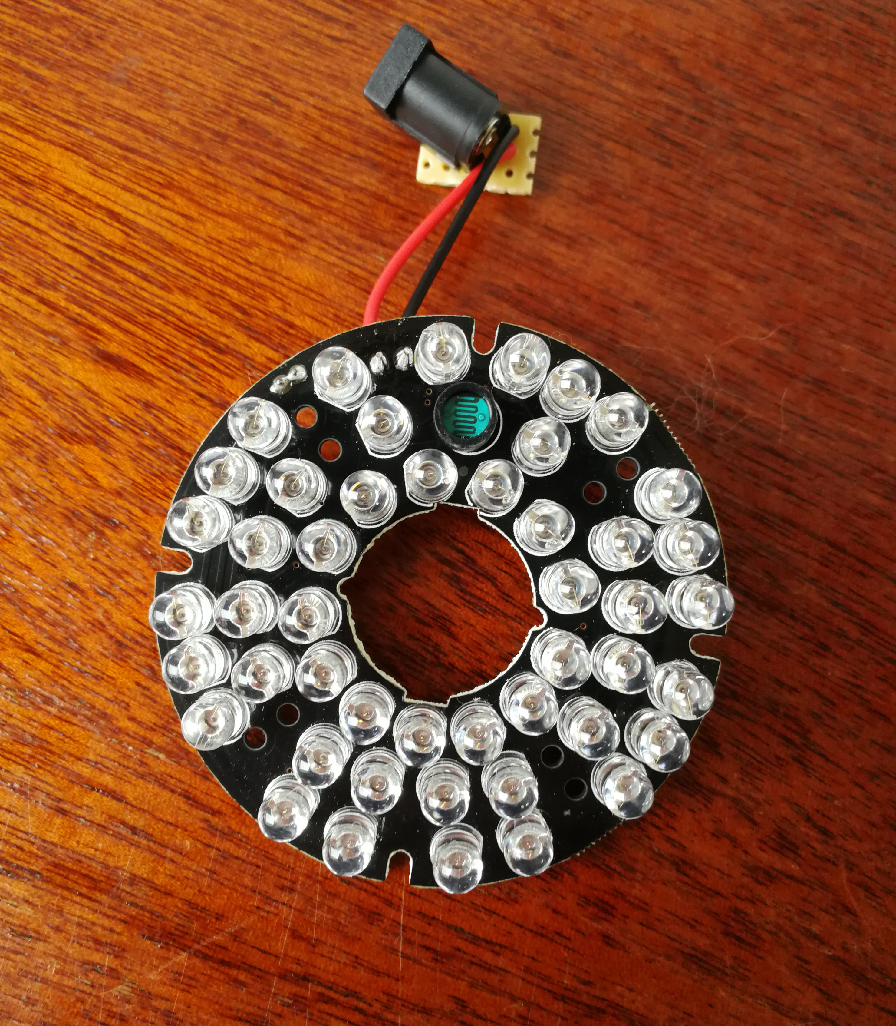
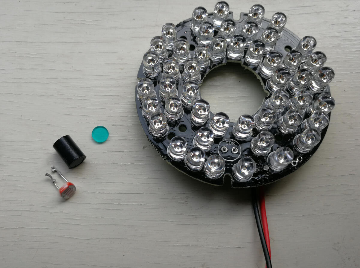
But there are a lot of infrared lights for security cameras. I ended up grabbing a 850nm 36 IR LED ring.
I do not have any connector for the 12V plug. So I soldered a barrel jack connection to the board:

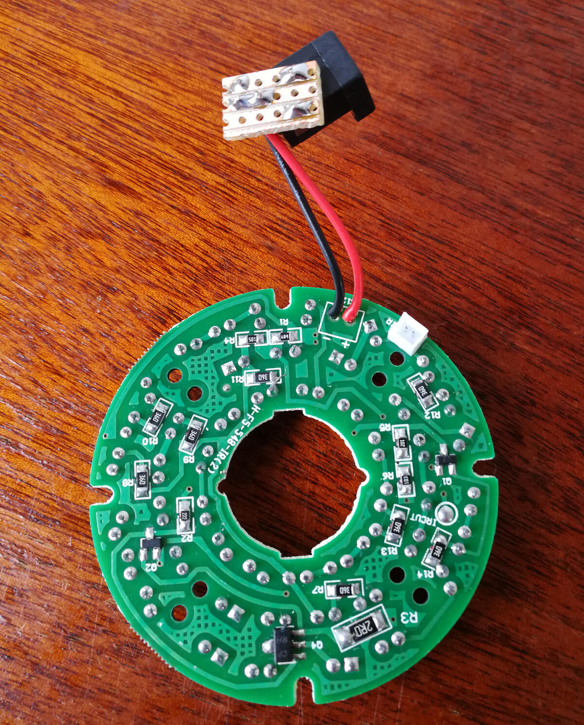
LDR circuity
The security camera LED ring has a problem, the lights only turn on in the dark. But the marker tracking system should work with a moderate amount of ambient visible light.
An light dependent resistor (LDR) is used to toggle the circuit. LDRs should have a high resistance in the dark and low resistance when lit. Directly measuring the LDR on the board confirms this:
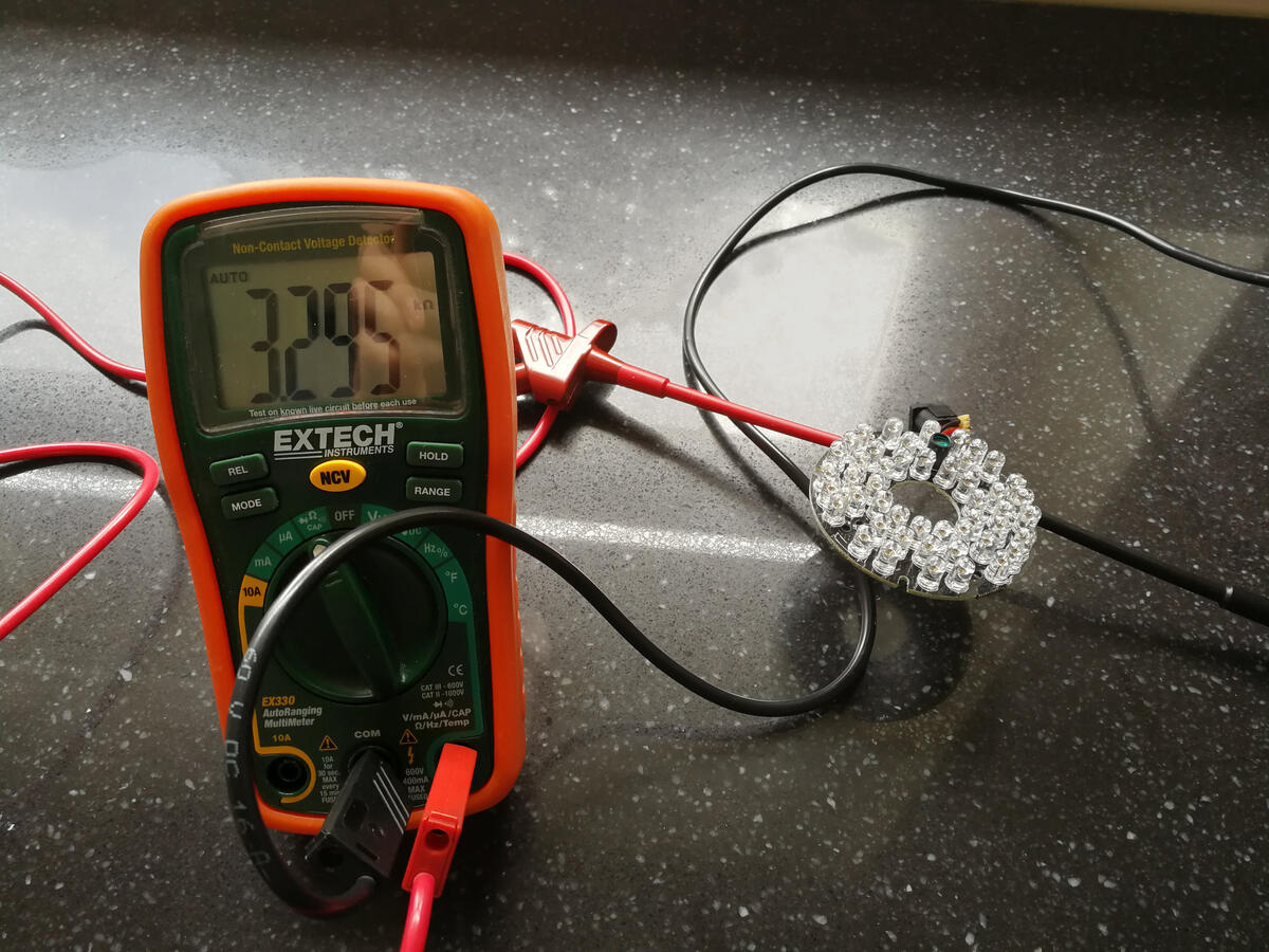
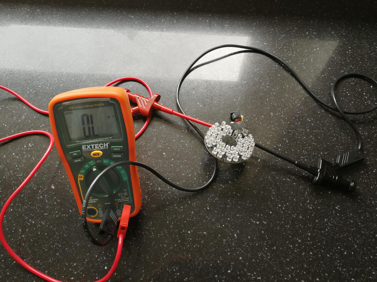
When sunshine hits the LDR the resistance is relatively low. It is a lot higher than expected, but still lower than a darkened sensor. Because, with the LDR covered by a bit of dark insulating tape my multimeter indicates there is no connection (open loop). In reality, I think that the resistance is simply very high, practically disconnecting the two terminals.
One solution to keep the light always on is to tape off the LDR. But since the tape easily gets dislodged, we'll go for the permanent solution: removing the LDR entirely. Removing it prevents any conductivity between the terminals, similar to the very high resistance with a dark LDR.
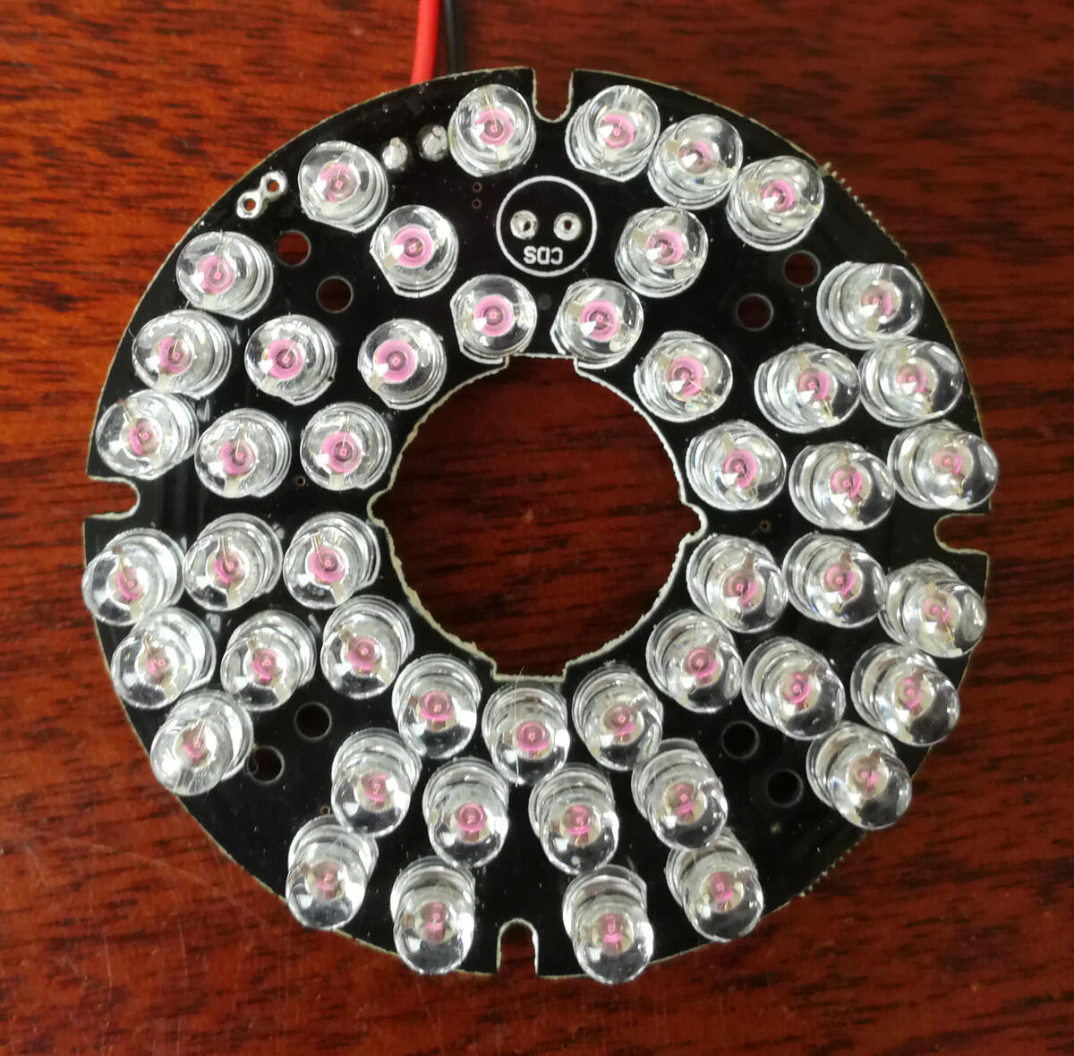
Success! After removing the LDR the LEDs are always on!
Interestingly the LDR was enclosed in a rubber cylinder with a small transparent blue cap. This blue cap is probably is an IR cut filter, so the sensor does not pick up the light emitted by the own circuit.
And note that since the LDR was acting as a switch, this is an excellent point to integrate a custom (electronic) switch in the future.
Light source effect
Let's have a look at the effect of this IR light source. The IR light is close to the camera and pointed at the scene. It is not yet around the lens because I don't have a good enclosure at this time. Nevertheless the effect is very pronounced:
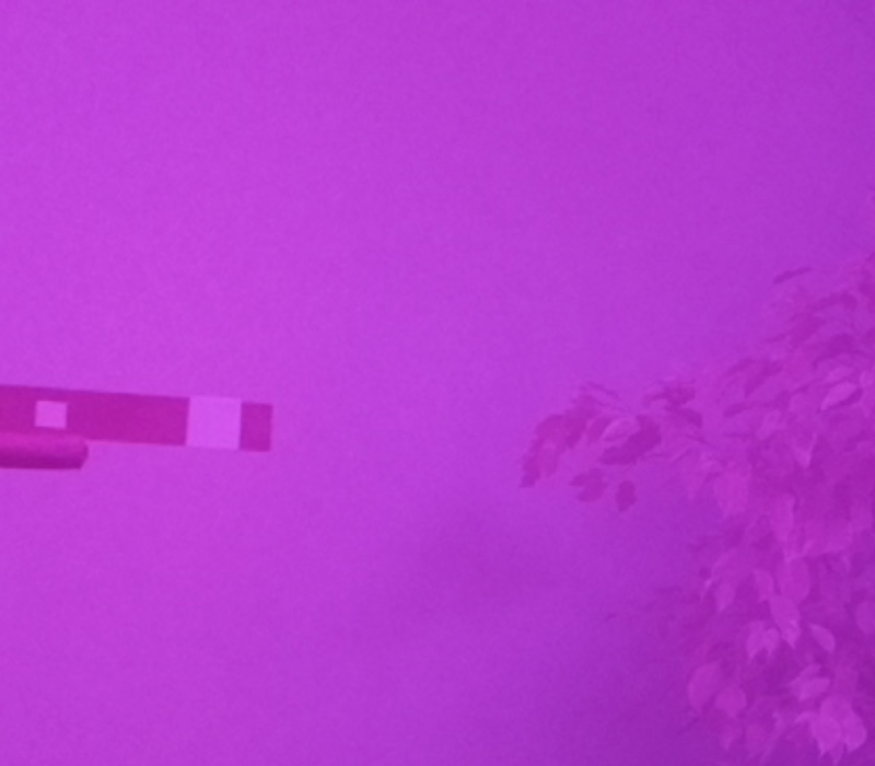
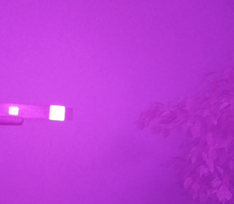
Both images are cropped parts of a RGB frame from the camera stream in sensor mode 6. With the IR light the reflective tape is very bright while the white wall in the back is hardly any brighter.
Concluding
The IR light source clearly separates the marker from none markers in the scene. This is already a highly encouraging result. But we may reduce the background noise even more by adding a proper IR filter. We'll look at several IR pass filters next.
Related
This post is part of the project Raspberry Pi marker detection
- Next post: IR pass filters
- Previous post: Picamera realtime high fps processing